The C2/C3 Corvette Chassis That Zora Built
Dateline: 7.31.19 – As seen in the January 2019 issue of Vette magazine, Illustrations by K. Scott Teeters – When the 1963 Sting Ray made its public debut in September 1962, it was a total, “WOW!” And it wasn’t just the Corvette’s stunning new looks; it was the all-new chassis and suspension. By late 1959 Zora Arkus-Duntov was in charge of Corvette engineering. When Bill Mitchell’s design team started work on project XP-720 (the all-new Sting Ray), Duntov was called in to set the parameters for an all-new chassis. The completed Sting Ray looked like the sportscar from another planet and the chassis had everything except four-wheel disc brakes. Today the running chassis looks like a buggy compared to the stout aluminum, steel, and magnesium chassis’ of the C5, C6, and C7 Corvettes. But in 1963 the top-performing L84 Fuelie engine only had 360 “gross” horsepower and 352-LB/FT of torque putting power-to-the-ground with 6.70×15 bias-ply tires. That’s not much twisting on the chassis, so the chassis was more than adequate.
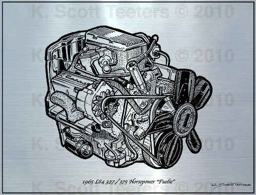
Even when the high-torque big-blocks arrived in 1965, for street use, the Duntov chassis could handle the job. The design didn’t start to show its limitations until the 1968 L88 racing Corvettes with wide tires started competing in long endurance races. Tony DeLorenzo once commented that after long 12 or 24-hour races, their Corvettes needed new frames. Their solution to this problem was a Logghe Brothers full welded-in roll cage. Greenwood’s wide-body Corvettes were so reinforced many asked, “Is there still a Corvette in there?” But for street use and spirited driving, the Duntov chassis served the Corvette well until 1982. Lets look at the chassis’ basics to see why it lasted so long
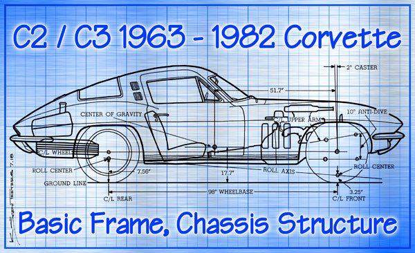
The genius of Duntov’s chassis was how much lower the center of gravity was. Chevrolet engineer Maurice Olley was a production car chassis and suspension expert when he designed the C1 chassis. As a racing expert, Duntov knew he had to get the center of gravity much lower. The C1’s chassis had a parameter frame with x-bracing in the center for rigidity. The car’s occupants sat on top of the frame. Everything measured from there; the cowl height, engine height, and everything else.
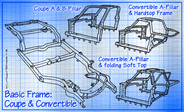
Duntov’s design eliminated the x-brace so that the occupants could be placed down inside the frame, dramatically lowering every data point from there. For rigidity the new frame had five crossmembers. Duntov then mounted the engine and transmission as low and as far back as possible and routed the exhaust pipes through holes in the second frame crossmember. The passenger compartment was pushed back as far as possible and the spare tire was mounted below the back of the frame and under the fuel tank.
The lowering of the engine/transmission and passenger compartment lowered the center-of-gravity from 19.8-inches to 16.5-inches. Moving major components as far back as possible in the shorter 98-inch wheelbase created a front/rear weight distribution of 47/53-percent. The engine centerline was offset 1-inch towards the passenger side because passenger footwell requirements were less than the driver’s. The extra offset reduced the transmission tunnel width and allowed the crankshaft and rear axle pinion to be on the same centerline. Ground clearance was just five-inches.
The build of the frame used boxed longitudinal sides with five crossmembers that were designed to suit the needs of styling. The new frame actually received computer analysis to determine the thickness needed for the parameters of the overall car. The front crossmember was welded to the sides and not bolted-on like the C1 chassis. The new frame with mounting brackets weighed 260-pounds, the same as the C1’s frame, but torsion rigidity increased from 1,587 lb/ft to 2,374 lb/ft per degree.
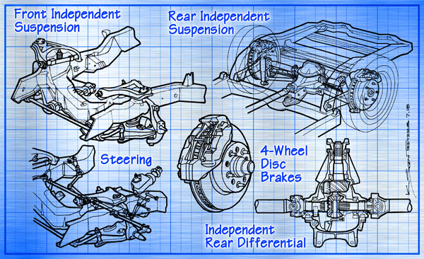
The C2/C3 suspension was a parts-bin marvel, although it didn’t seem that way. Duntov wanted an independent rear suspension and was immediately told, “No! It’s too expensive.” To get around this, Duntov used almost 60 full-size passenger car front suspension parts, including pressed-steel wishbones and ball-jointed spindles, and just rearranged them. The parts had already been engineered and proven, thus saving production cost. With a 9-degree slope, the wishbones gave an anti-dive reaction upon heavy braking. Then the inner pivot points were lowered to raise the roll-center to 3.25-inches above the ground. A recirculating-ball steering unit was placed behind the suspension and used a hydraulic damper to reduce kickback. All of these changes were very apparent when combined with the right shocks and anti-roll bars when the cars were first driven and tested. The money saved was more than what went into the rear suspension.
The independent rear suspension started with the differential pumpkin bolted to the 4th crossmember with the driveshaft as a device to control forward thrust from the wheels. Axle half-shafts with universal joints are on each side of the differential. Steel box-section control-arms carry the outer half-shafts and attach to the rear frame kickup assembly. Shims at the forward pivot-points are used to adjust toe-in alignment. Strut rods attach to the strut-rod bracket bolted below the differential and connect to the rear spindle support on the control-arms. The nine-leaf transverse spring with polyethylene liners between each leaf to reduce noise, mounts under the differential and is sprung against the rear portion of the control arm with long bolts. Duntov’s proposal to use a transverse leaf spring was not well received by Chevrolet chief engineer, Harry Barr, but no one could come up with a better plan.
For its time, Duntov’s chassis worked very well, but I’m sure that no one imagined it would be used for 20 years. The design proved to be easy to update. Disc brakes were in development when the Sting Ray came out and arrived on the 1965 model. When the new Mark IV became available in 1965 the suspension got stiffer front springs and larger diameter front and rear stabilizer bars. The new chassis was totally adaptable and could be made near-battle-ready with suspension component changes. During the 20-years of Duntov’s chassis, Racer Kits included; the 1963 Z06, 1967-1969 L88, 1970-1972 LT-1 small-block ZR1, and the 1971 big-block ZR-2. And from 1974-1982 there was the FE7 Gymkhana Suspension for spirited street driving. On the street, Duntov’s chassis could easily handle the 327 Fuelie to the LS6 454.
In the ‘70s chassis changes were made to conform to tightening regulations. Starting in 1973 the chassis had to handle the new 5-mph crash bumpers and steel side-door guard beams. In 1975 catalytic converters helped reduce emissions, but cloaked engines. A steel underbelly had to added to the chassis as a heat shield against the very hot converters. 1980 saw a big weight reduction from 3,503-pounds to 3,336-pounds thanks to an aluminum differential, lighter roof panels, thinner material on the hood and doors, and the use of the aluminum L84 intake manifold on the standard engine. The following year, a fiberglass-composite rear leaf spring helped shed 29-pounds. Early ‘80s Corvettes don’t get much respect because their restricted engines, but their drivetrain and suspension was as good as ever. An early ‘80s Corvette with a classic SBC crate engine would make for a stout performer.
Yes, Duntov’s chassis looks crude by today’s standards. But Corvette development is always empirical. If it weren’t for the C2/C3 chassis, there never would have been a C4 chassis, and so it goes. – Scott

Corvette Chassis History, Pt 1 – C1 Chassis – HERE
Corvette Chassis History, Pt 2 – C2/C3 Chassis – HERE
Corvette Chassis History, Pt 3 – C4 Chassis – HERE
Corvette Chassis History, Pt 4 – C5 Chassis – HERE
Corvette Chassis History, Pt 5 – C6 Chassis – HERE
Corvette Chassis History, Pt 6 – C7 Chassis – HERE
